Intro
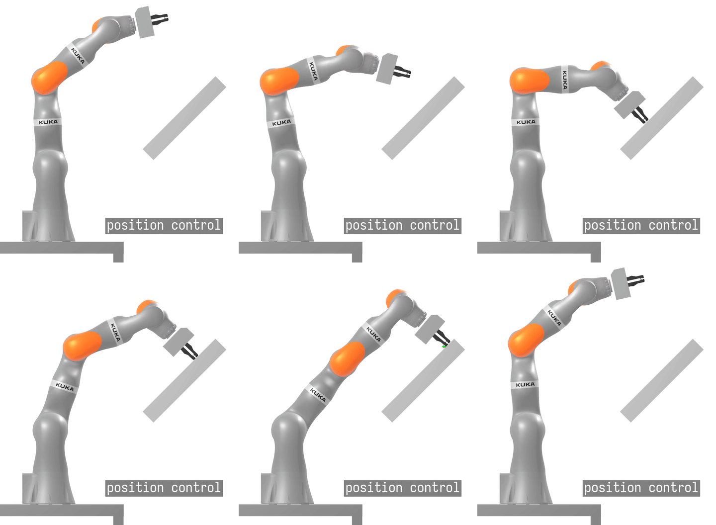
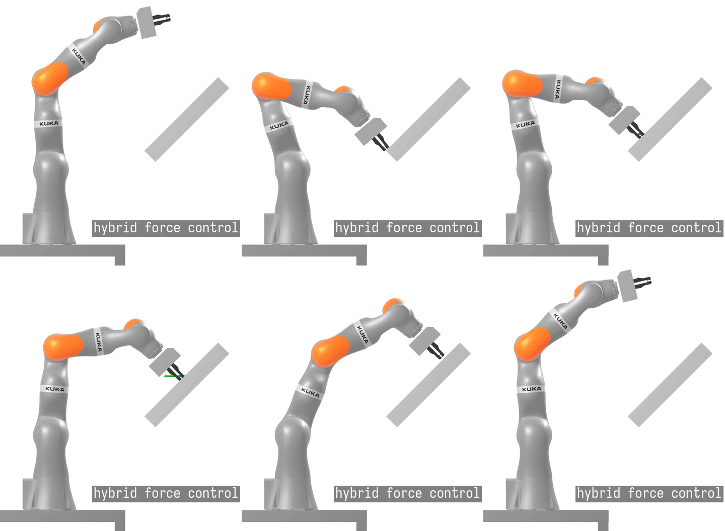
This problem is fit to highlight the limitations of position controllers, which may struggle with unmodeled dynamics due to contact. To make the derivations illustrative and tractable, the book studies the problem for a planar case. The proposed implementation does likewise. But, in contrast with the book, which used a very simple cartesian 2 DoF robot, a planar version (3 DoF) of a real collaborative robot KUKA iiwa is explored here.
The author then adds another property lacking in the book: the slope-tracking motion isn't studied in isolation here. The control sequence delivers the robot's end effector to the sloped shelf's starting point, and then returns end effector to the default configuration after reaching the shelf's end.
 Frank L. Lewis: "Robot Manipulator Control: Theory and Practice", 2004
Two versions of this control sequence differ in how slope tracking is implemented: via position or force control.
Notation
Let's begin at the beginning, namely, with Newton's 2nd law of motion: f = M * a. The robot isn't a material point, hence we progress from scalar to multi-variate formulation:
τ = M(q) * v_dot + C(q, v) * v + τ_g(q) (1)
Aside from this formulation being multi-variate, another complication exists: this vector space isn't Cartesian. Instead, the specified vectors are in generalized coordinates. But bear with me. Our robot, KUKA iiwa, normally has 7 DoFs, but having some joints locked in the planar mode, is left with just 3 active DoFs.
Thus τ, q, v, v_dot are column 3-vectors, representing torque, position, velocity and acceleration of each of the robot's joints. Generalized coordinates aren't easy to think about, but are great for understanding (and controlling) what's happening to the robot's joints at the moment.
Having defined the vector variables, let's explore the remaining quantities of (1):
Mis a3x3configuration-dependent inertia matrix of the robotCis a3x3matrix representing gyroscopic and Coriolis forces arizing from ongoing robot's motionsτ_gis a 3-vector that captures the gravity force projected on robot's joints
Baseline: Position Control
The complete computation won't be derived here as we have a physics simulator available to exploit. inverse_dynamics routine allows to estimate robot's torques needed to withstand inertial, gravitational and other external forces, provided the estimate of robot's state.
τ_0 := inverse_dynamics(state=(q, v, v_dot=0), t=τ_g(q))
Putting the above into (1) results in the torque, which achieves stabilization of the robot:
τ_stabilizing = τ_0 - C(q, v) * v
For control objectives, that go beyond mere stabilization, PID terms are added:
τ_commanded = τ_stabilizing + PID(q, v)
NB. Contact-rich controllers normally use PD, and not PID: it isn't safe to integrate the irreducible error due to planned contact.

Alternative: Hybrid Force Control
"Hybrid" in the method's name stems from the fact that the different control laws are used to effect change onto distinct spatial dimensions of the problem. A fundamental result in robotics (see N. Hogan's work) states that it's impossible to simultaneously control both force and velocity along any given spatial axis. E.g.: the control may command a target speed, but the resulting interaction forces will be due to the environment. Vice versa, the control may command the force applied and experience whatever velocity that environment admits at this force.
However, nothing prevents control from doing one thing along axis X, and another along Z. This exactly is what this controller does. Many practical applications call for this approach, including our problem. When we target to brush along a slope, it's only natural to regulate the tangential velocity and normal force. The dynamic equation which produces this behavior is τ_commanded = τ_stabilizing + τ_tangential_ctrl + τ_normal_ctrl. It conveniently builds upon the above-listed solution. Here we explore the two latter new terms.
τ_tangential_ctrl = PD(J^T * pe_tang, J^T * ve_tang)τ_normal_ctrl = PD(J^T * fe_norm, J^T * ve_norm)
Again, we regulate the error with PD-control in position and velocity, and now in force too. But the curious part is J^T, which is a kinematic jacobian. The controller from previous section worked completely within the generalized (inner) coordinate space. But axes used in hybrid control specification are the axes of cartesian task space. This jacobian is a linear operator that allows the forward and inverse maps. pe, ve, fe stand for position, velocity and force error. Only the tangential (X) component of pe, ve is used in τ_tangential_ctrl. In its turn, τ_normal_ctrl uses the normal (Z) component of the force error fe. The use of ve_norm in τ_normal_ctrl is a technicality. Force measurements normally aren't differentiable, and normal velocity is used as a proxy in this PD.

Comparison
Both graphs present values in the shelf's coordinate frame.
 Position error during the brushing motion. Readings closer to 0.0 are better.
 Sensed forces: the target normal force along Z axis is 10 N. Non-zero forces are registered when manipulator is in contact.
Conclusion
We observe in visualisations and in the previous section that hybrid controller (maroon) maintains contact during the most of brushing motion against a slope, while position controller (red) does not.
It may be seen from graphs, that even the hybrid controller didn't reach the target normal contact force of 10 N. Additionally, this hybrid controller tracks the tangential pose worse than the position controller.
Thus a better tuning of the hybrid controller is possible, and we expect to see new works on this topic here. But in the meantime, the source code for both controllers is available here.
